ESP8266(Arduino) interface with Firebase: Aim: Make such application in which LED can be control from mobile or website from any remote location where internet connectivity is available. Requirement: 1 ) ESP8266 -E12 WiFi module as shown in picture. You can get start and setup it with help of this post. 2) Download and install firebase-arduino-master library in Arduino IDE. 3) Need gmail account for create Firebase project. Step 1: Go to https://console.firebase.google.com and create new project. Step 2: Click on Database now you will see the host name show in image Copy that host name and past in Arduino code given below at line #define FIREBASE_HOST "fir-app-example.firebaseio.com" Step 3: Go to Setting>Project Setting>SERVICE ACCOUNTS>DATABASE Secretes. Copy "Database Secrets" Shown in below image Copy and paste Database Secrets at the line in code #define FIREBASE_AUTH " example sd2asdasdasdasd2asd3asd2asd2as32das3d2as2da3&q
Posts
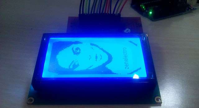
JHD12864E interfacing with Arduino Uno( 128x64 Bit MAp Graphics LCD) : Requirement : 1 ) JHD12864E LCD 2 ) Arduino 3 ) Connecting wires Aim: Convert and display JPEG image on Graphics LCD as Bitmap image Step 1 : Download and put Glcd library in Documents/Arduino/library folder GLCD library Step 2 : Download BMP-To-LCD software to convert JPEG image to BMP array BMP-TO-LCD Step 3: Make connection of LCD to Arduino UNO as shown in figure. Step 4: Download any image from internet. Step 5: Open image in Paint Step 6: Step7 : Step 8: Step 9: Click on resize without selecting area Step 10: Save image as 1.bmp Step 11 : open Image in BMP-LCD software And click on Genarate code Copy that genarated code in Arduino sketch Step 12: Copy Paste code in bitmaps.h with some modification as shown in below image Main sketch is as shown below image

Download English Dictionary words for Microcontroller based Text to Speech (TTS) convertor: What is TTS? Speech synthesis is the artificial production of human speech. A computer system used for this purpose is called a speech computer or speech synthesizer, and can be implemented in software or hardware products. A text-to-speech (TTS) system converts normal language text into speech; other systems render symbolic linguistic representations like phonetic transcriptions into speech. Basic architecture is explained in following block diagram. Microcontroller feed with text data from any interface . microcontroller make tokens of that string into and compare appropriate soud file per word from data bases. After getting all index of each word of string micro controller play sound files one after another with proper delay in words. As per post title I am going to use Python script to make my own speech files database(format in mp3). Prerequisite : 1) Installed python 2.7 ( Down

Raspberry pi 3 kernel module compilation: Raspberry pi 3 kernel module compile : Step 1: Update current kernel $sudo apt-get update $sudo apt-get upgrade $sudo apt-get install bc $sudo apt-get install gcc Step 2: Download linux headers for current kernel version $uname -r > 4.4.26-v7+ copy kernel version and goto url https://www.niksula.hut.fi/~mhiienka/Rpi/linux-headers-rpi/ and find your kernel version here in my case linux-headers-4.4.26-v7+_4.4.26-v7+-2_armhf.deb 20-Oct-2016 21:07 6891064 Download it Step3: Now install the downloaded inux headers. $sudo dpkg -i linux-headers-4.4.26-v7+_4.4.26-v7+-2_armhf.deb it takes while let it be complete without interrupt process. Step 4 : $cd $mkdir kmod $cd kmod $sudo nano hello-1.c copy and past following programe in file then save it [^X] /*hello−1.c − The simplest kernel module.*/ #include < linux/init.h > //linux/init.h Macros used to mark up functions e.g., __in

2.4 Ghz channel scanner using NRF24L01 RF Transreceiver : What is 2.4Ghz scanner: My requirement behind this project is I want to make such device which can sniff 2.4Ghz ISM frequency band. But after some research its bit hard and trick to make such device. But I figure it out to made such a device which can locate the particular channel on which data is transmitted. their are some ready made examples for Arduino but none of with GUI that can be easy to understand. here I developed GUI base 2.4GHZ channel scanner( NOT SNIFFER :( ). Here I used channel range from 1 - 126 means NRF2401 having frequency range of 2.4Ghz - 2.529GHz which can be divided in 126 channels each one of 1Mhz. so if you want to find wifi channel frequency for particular standard you need to map NRF2401 channel with the standard channel. see the standard 802.11b/g/n below and map 2.4Ghz - 2.529GHz = 1 - 126 with this range Required : 1) Arduino 2) NRF24L01 3) Microsoft Visual Studio 2015
Working on scrolling display: From long time I wish to have my own LED scrolling display now I got some time to work on it. Here some Photo of it working on simple LED scrolling display. Further extension of this module is fetch Facebook notification using wifi and display on scrolling LED display and using Bluetooth display mobile messages on it. ;). Day1 : Day2: Day 3: Day4:
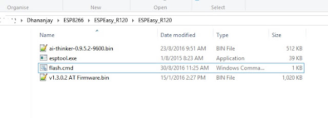
ESP8266 AT firmware : As in previous post we have seen ESP8266 as stand alone but some time in some application we need only WiFi connectivity or simple WiFi module that can be controlled through AT commands. we can program ESP8266 for work on AT command. Required: 1) ESP8266 3) USB to serial convertor Step 1: Setup ESP8266 as given in this post. Step 2: Download ESP8266 AT command firmware by AI Thinker. Step 3: press and hold Flash button(GPIO0 = GND) then press Reset button(RESET pin = GND) release RESET button then Flash button now ESP8266 goes into Flash mode. Step 4: Extract downloaded rar file. Step 5: open "flash.cmd" file and wait for complete flashing process. Step 6: Setup local Server for receive data. I use TCPClientServe software which allow you to create local server and client to send and receive data over TCP Download Here Enter port 6000 and start listening. Step 7 : Open Serial terminal at baudr
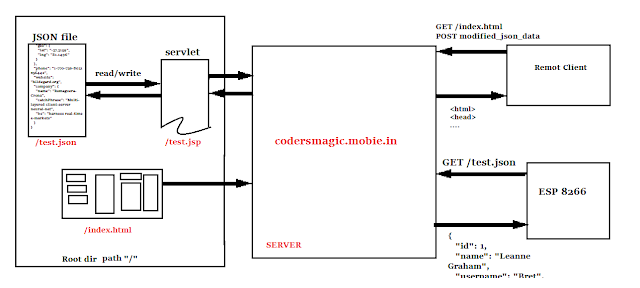
Fetch and parse JSON on ESP8266 wifi module : Use case: I want monitor particular json stored on server which can be modify by website from remote distance. It can be useful where you can modify control bits from website and change GPIO status at ESP8266 side. 1) Home automation 2) Information parsing 3) Staus monitoring 4) non realtime notification This system work on principle on monitoring files. Feature : Stand alone operation of ESP8266. Uses JSON parsing so data extraction is very easy. Required : 1)ESP8266 2)Arduino or any USB to serial converter with 3.3v or 5v power connection pin out. Basic Working: ESP8266 : It uses the local router to connect internet and fetch JSON from server using HTTP get request after every second parse it and display JSON variables on serial monitor(you can compare them and change GPIO for device control). Shown in diagram it send GET request at server and server send back HEADER + JSON to ESP8266 HTTP request